
(:notabledit:)
RetroCade User Guide Contents
Windows Quick Start
RetroCade User Guide
Windows Quick Start
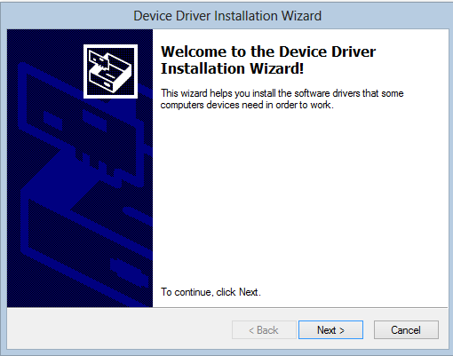
Install RetroCade Synth
- Download RetroCade Installer
- Unzip to a temporary directory of your choice and run the included setup executable.
At this time the ZPUino IDE does not work if there are spaces in the path, the installer will place the ZPUino IDE in the root of your C: drive instead of in Program Files. If you do not want this to happen then choose "Custom" install type and deselect the ZPUino IDE. You will not be able to edit the RetroCade sketch if you deselect this option.
- The installer will prompt you to install the RetroCade Device Drivers. Important: To install the Papilio Drivers under Windows 8 follow this Guide.
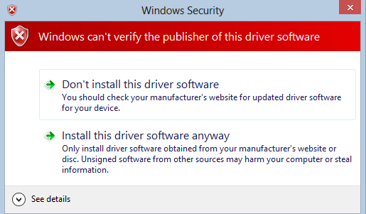
- Windows Security may display a warning message. Choose, "Install this driver software anyway".
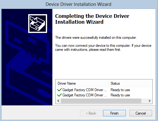
- The drivers should be successfully installed.
Upgrade Hardware
Upon receiving your RetroCade Synth the first thing you will want to do is install the latest firmware to the hardware to ensure you have all the latest bug fixes and features. The latest firmware is included with the Windows Installer and can be accessed from the Start Menu.
- Ensure the RetroCade MegaWing is plugged into the Papilio Pro FPGA board.
- Plug the Papilio Pro board into a free USB port using a standard Mini-B USB cable.
The RetroCade Synth does not ship with a Mini-B USB cable, chances are good that you will already have one on hand.
- Open your Start Menu and click on the "Upgrade to RetroCade-[Version] Bit File".
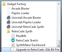
- Windows XP and Windows 7 users will have this entry under "Start\Gadget Factory\RetroCade"
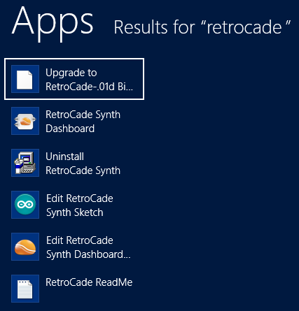
- Windows 8 users should press the "Windows" button on their computer and type in "Retrocade" to see all RetroCade start menu options.
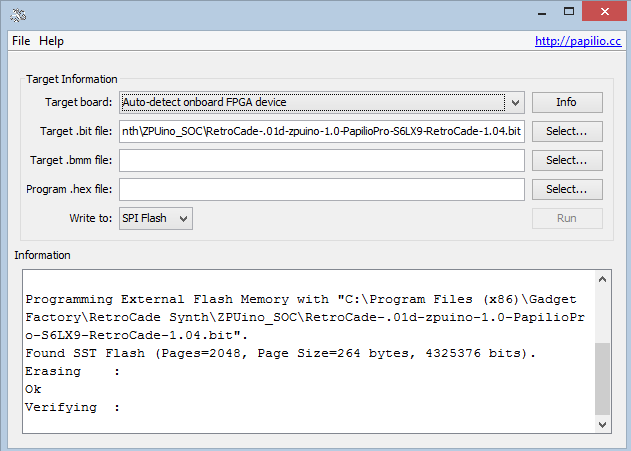
- The Papilio Loader should pop up and write the latest firmware to your hardware.
Overview
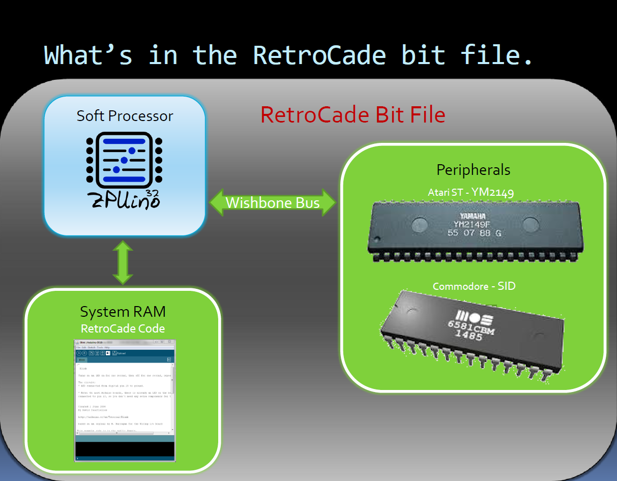
Architecture
RetroCade Block Diagram
RetroCade Presentation
http://youtu.be/6E-USsejc5o
Watch this presentation to learn the nitty gritty details of the RetroCade's internals.
FPGA
What is an FPGA?
- FPGA�s (Field Programmable Gate Array) are like the rewritable CD�s of electronics.
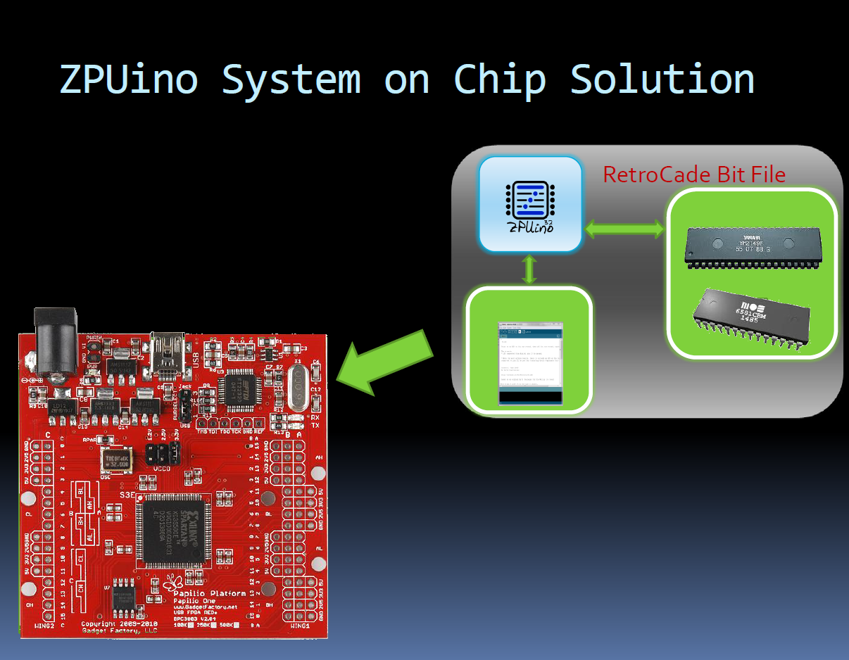
- You use a bit file to burn a hardware design onto an FPGA.
- When you burn a hardware design to an FPGA it BECOMES that hardware.
- Hardware designs can be anything you can dream up, in this case it is a ZPUino processor with Open Source recreations of classic audio chips connected.
- You can easily burn other hardware designs to the FPGA. After loading the RetroCade bit file you can play PacMan by loading a bit file that turns the Papilio FPGA into a PacMan Motherboard!
Why use an FPGA?
- The FPGA allows us to do things that would not be possible otherwise!
- We can connect multiple audio chips at the same time.
- We can connect as many instances of an audio chip as can fit in the FPGA. (I.E. a 12 voice SID chip!)
- We can make a library of hardware based digital effects and connect them to the outputs of the audio chips.
- The audio chips are connected inside the FPGA so no messy wiring is needed.
- The final solution is a very fast HARDWARE solution, not software emulation.
Microcontroller vs. FPGA?
- The Arduino is an example of a Microcontroller and the Papilio is an example of an FPGA.
- The Arduino uses a sketch to tell it what to DO.
- The Papilio uses a bit file to tell it what to BE.
- For the RetroCade, we load a bit file that tells it to BE an Arduino compatible system with audio chips attached.
- Once we tell it to BE an Arduino compatible piece of hardware we then load the RetroCade sketch to tell it what to DO.
- Sketches are loaded with a modified version of the Arduino IDE!
ZPUino
What is ZPUino
- ZPUino is the heart of the RetroCade Synth project.
- 32 bit soft processor running at 96Mhz.
- Uses a modified version of the Arduino IDE to load sketches.
- Wishbone bus for connecting peripherals such as our audio chips.
- Actively maintained and developed by Alvaro Lopes.
- To learn more visit: http://www.alvie.com/zpuino
Block Diagram
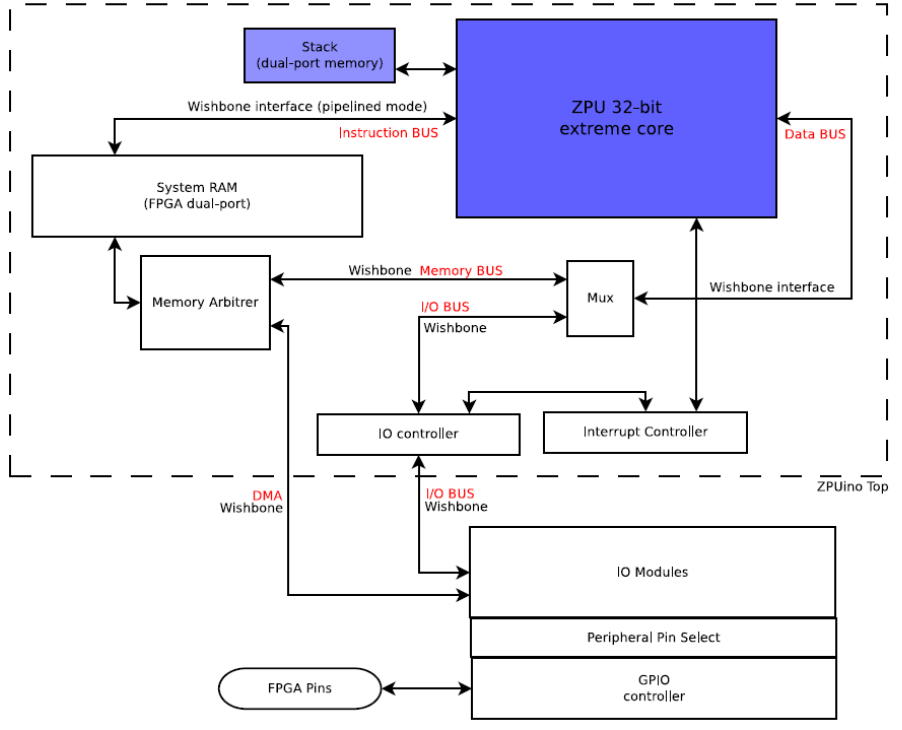
ZPUino System on Chip
Audio Chips
Audio Chips
- The audio chips used in the RetroCade SOC are Open Source VHDL implementations that recreate the SID and YM2149 inside the FPGA.
- It is not software, the VHDL files tell the FPGA how to connect logic gates inside the FPGA to make real hardware.
- The VHDL files are created by talented VHDL developers by studying datasheets, observing the original chips, and even from interviews with the original designers.
- VHDL Developers like MikeJ@FPGAArcade.com and Jan Derogee decided to release their work as Open Source, which allowed us to connect them to the ZPUino and make the RetroCade Synth.
- There are many more VHDL definitions for other classic audio chips, like the NES and Atari 2600, that can be implemented.
- The designs are not perfect, but they are VERY good. Since they are Open Source we will be able to fix any bugs.
The C64 SID design does not currently implement the analog filters. Everything else is complete and working, we expect to use the FPGA DSP blocks to implement the analog filters. This is our highest priority for the RetroCade Synth.
Using RetroCade Synth
Use MIDI Keyboard
Once you are running the latest firmware you are ready to connect a MIDI keyboard or controller to the RetroCade Synth and start playing the various sound chips. All features of the sound chips are mapped to MIDI Control Changes so if your MIDI keyboard has knobs and sliders they can be mapped to control all functionality of the RetroCade Synth. Refer to the RetroCade MIDI CC-NRPN Chart for more info. There are two options to control which voice you are playing, you can use the joystick and the LCD screen on the RetroCade to select a voice or you can change the channel on your MIDI keyboard. The voices are mapped according to the following chart:
| MIDI Channel | Sound Chip | Sound Chip Voice |
|---|---|---|
| 1 | SID | Voice 1 |
| 2 | SID | Voice 2 |
| 3 | SID | Voice 3 |
| 4 | YM2149 | Voice A |
| 5 | YM2149 | Voice B |
| 6 | YM2149 | Voice C |
| 7 | Mod File | Kick - Left keys : HiHat - Right keys |
Use RetroCade Control Dashboard

The RetroCade Control Dashboard is an optional interface that adds a nice, intuitive way to control all the features of the RetroCade sound chips. If your MIDI keyboard does not include knobs and sliders, or you just want an easy to use interface then take a look at the RetroCade Control Dashboard.
Start the RetroCade Control Dashboard
- Open the Start Menu and click on "RetroCade Synth Dashboard"
- Windows XP and Windows 7 users will have this entry under "Start\Gadget Factory\RetroCade"
- Windows 8 users should press the "Windows" button on their computer and type in "Retrocade" to see all RetroCade start menu options.
Connect RetroCade Control Dashboard to RetroCade Hardware
There are two ways the dashboard can connect to the hardware:
1) When the RetroCade Hardware is connected to a USB port a virtual COM port connection is established. The RetroCade Control Dashboard can use this virtual COM port to communicate with the RetroCade Hardware. The benefit of this option is that no MIDI cables or adapters are needed. The downside of this option is that you cannot debug the RetroCade sketch over the com port if you use this option.
2) The RetroCade Control Dashboard can also communicate with the RetroCade Hardware using a USB MIDI cable that is connected to your computer on one side and the RetroCade MIDI In port on the other.
- Ensure the RetroCade Hardware is plugged into a USB port.
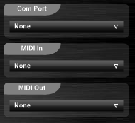
- Use the drop down boxes to select the RetroCade's virtual COM port or a USB MIDI cable.
Use the Computer Keyboard to play Notes
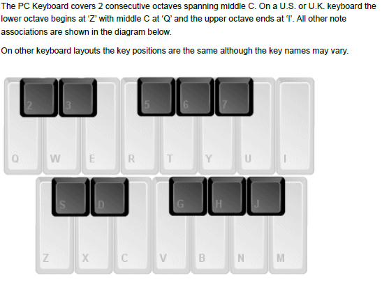
Connect a MIDI Keyboard
A MIDI keyboard can be connected directly to the MIDI in connector of the RetroCade Hardware or it can be passed through the RetroCade Control Dashboard. A MIDI USB cable is needed to pass a MIDI keyboard through the dashboard. To do so simply connect your MIDI keyboard to the MIDI in of the MIDI USB cable and use the MIDI In drop down box to select it. Any keys played on the MIDI keyboard will be sent out through MIDI Out and the Com port.
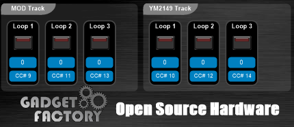
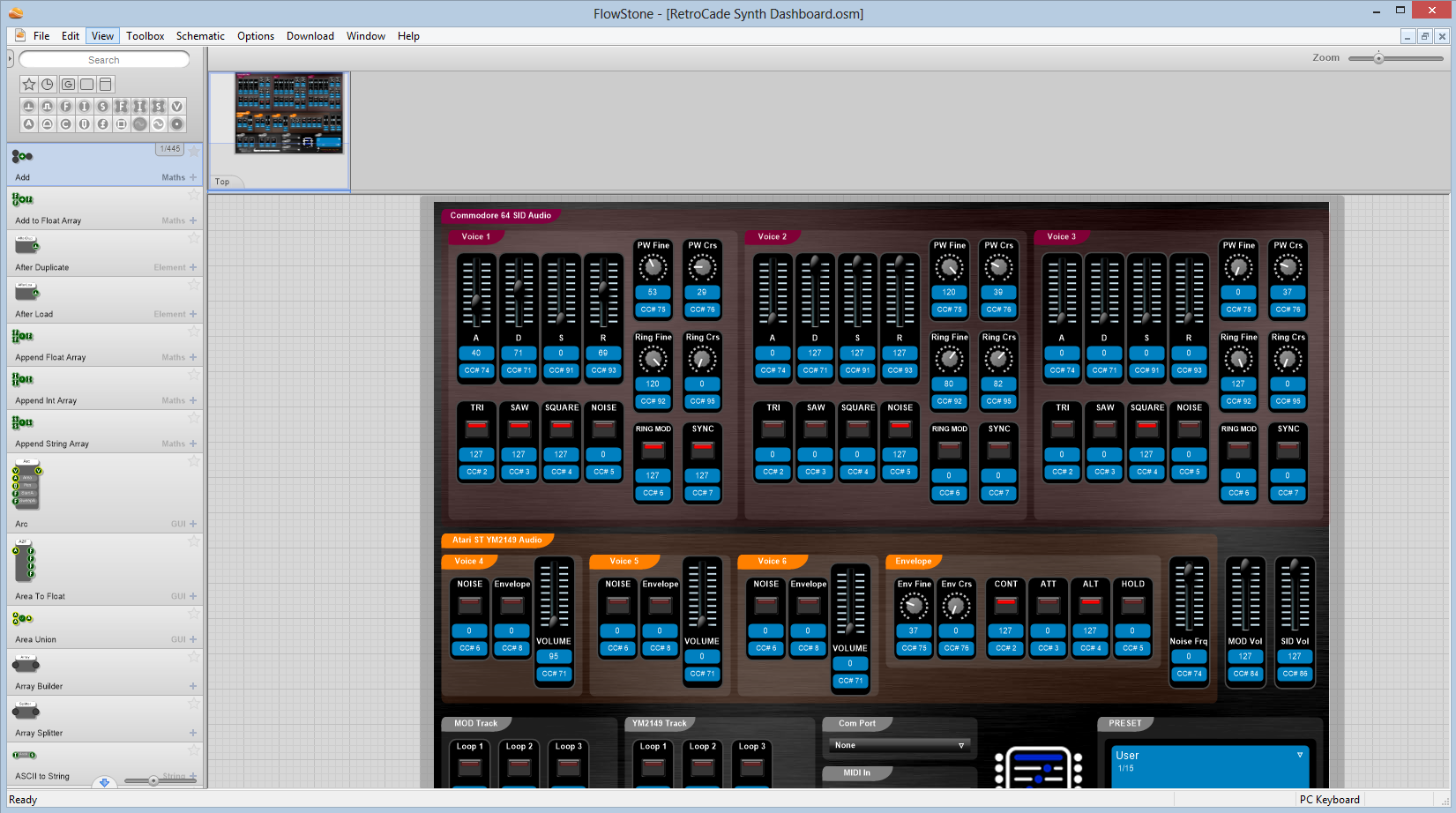
To quickly see the default Control Changes that are defined for the RetroCade Hardware look at each element of the RetroCade Control Dashboard. Under each element is a CC number. In the following image you can see that for Voice 4, which is the first voice of the YM2149, a CC of 6 turns Noise off or on. If your MIDI controller is set to Channel 4 and you send a CC of 6 you will hear Noise toggle. Likewise, if you change to channel 7 or 8 the same CC will be active for YM2149 voice 2 and 3.
Zooming
Keyboard shortcuts control the zoom level of the stand alone executable.
| Function | Key | Note |
|---|---|---|
| Fit to Screen | Left Arrow | Only in Full Screen Mode |
| Normal Size | Down Arrow | |
| Toggle Full Screen Mode | Up Arrow |
Presets
Presets can be used to define custom instruments for the RetroCade sound chips. There are a number of presets that are pre-defined for SID Voice 1.
- Use the left/right arrows or drop down arrow to select different presets.
- To define your own presets:
- Select a preset slot you would like to modify.
- Make changes to any of the settings for any of the voices.
- Save the changes to a custom presets file using the File dropdown.
Play MOD and YM Tracks
The RetroCade firmware includes some sample MOD and YM files that can be played as soon as a control connection is established.
- Select any of the track buttons to start playing a sample track.
Convert YM Tracks to YMD
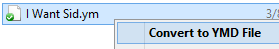
YM tracks can be converted to the format needed by the RetroCade Synth by right clicking on a YM file and selecting the Convert to YMD File option. The YMD file should appear in the same directory as the ym file.
The MOD and YM tracks that are shipped with the firmware are located in the SmallFS filesystem that resides in SPI Flash. Any of the tracks can be overridden by placing a corresponding track onto the SD card. Files named track[1-3].mod will override the mod tracks and files named track[1-3].ymd will override the YM tracks. The YM files need to be converted into ymd (YM Data) files.
Making the RetroCade your own!
Modify the RetroCade Sketch
ZPUino IDE
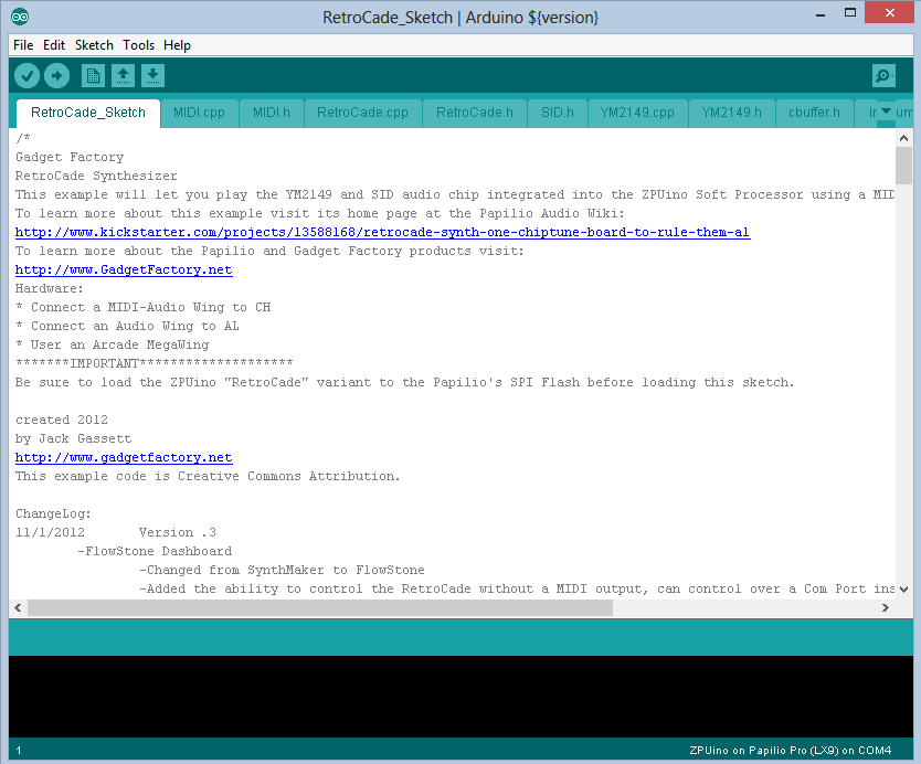
The RetroCade Synth was conceived from the very beginning as an Open Source project that is easy to hack and make your own. All of the RetroCade Synth features are defined by an Arduino style sketch in order to make it as accessible to as many people as possible. All functionality such as Control Change mapping, default settings, behavior, and file system support can be modified and expanded in any way that you desire. The Windows Installer includes a specially modified version of the Arduino IDE that is used to program the RetroCade sketch to the ZPUino Soft Processor. It's very easy to get started with modifications, there are no complicated development environments or toolchains to setup, just open the sketch from the start menu and start making changes.
Start the ZPUino IDE to make changes to the sketch
- Open the Start Menu and click on "Edit RetroCade Synth Sketch"
- Windows XP and Windows 7 users will have this entry under "Start\Gadget Factory\RetroCade"
- Windows 8 users should press the "Windows" button on their computer and type in "Retrocade" to see all RetroCade start menu options.
Load the RetroCade Sketch to your RetroCade Hardware
- Ensure the RetroCade Hardware is plugged into a USB port.
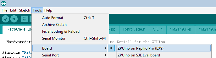
- Select "ZPUino on Papilio Pro (LX9)" as the Board type.
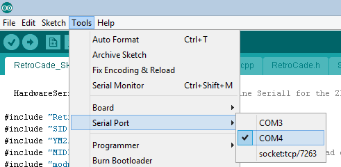
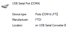
- Connect to the RetroCade Serial Port (If unsure of serial port, see tip below)
- Make your changes to the RetroCade Sketch
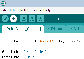
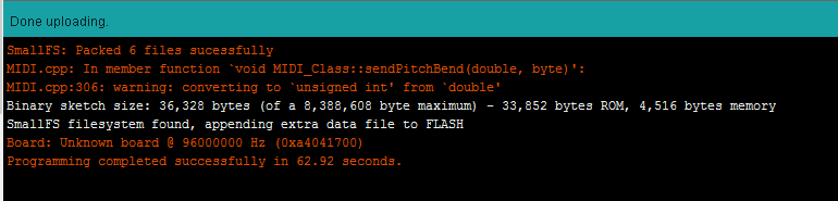
- Click the "Upload" icon. (For verbose output, see tip below)
- Observe the output to verify the changes have been programmed.
Add SmallFS files
The Papilio Pro includes a 64Mb (8MB) SPI Flash chip that has lots of space to store data such as MOD and YM files. The SmallFS file system is a special ZPUino file system that has very low overhead, it does not implement a FAT file structure, and is much faster then SD cards. It is very easy to use, to load files to the SmallFS file system you simply create a "smallfs" folder in the RetroCade sketch directory and place whatever files you want included in SmallFS there. The ZPUino IDE will handle formatting and uploading your files into SPI flash. Look at examples in the modplayer and ymplayer source code to see how to access your files from the RetroCade sketch.
To quickly find the correct serial port: Unplug the RetroCade and note what ports are available, plug it in and look at the available ports and see what new ports show up. If two ports show up the correct one is always the second port. If you are having trouble look at the Device Manager and look for "FTDI Serial Converter B".
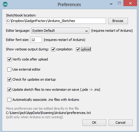
If you want to see more information during the compilation and programming phase then turn on verbose output from the File/Preferences dialog box.
Modify the RetroCade Control Dashboard
FlowStone
The RetroCade Control Dashboard was made in a popular software application called SynthMaker. SynthMaker has recently been renamed to FlowStone and has been expanded to do more then make synthesizers. We do not use any of the synthesizer functionality, all audio generation is handled by the RetroCade Hardware, we simply use FlowStone to make an attractive and hackable Control Dashboard. FlowStone has a free edition that allows anyone to make modifications to the RetroCade Dashboard, those changes can be used within the free edition of FlowStone or shared with the RetroCade community. The paid version allows us to generate a Windows EXE and VST plugin version of the RetroCade Control Dashboard.
- To modify the RetroCade Control Dashboard you must first download and install the free version of FlowStone.
- Open the Start Menu and click on "Edit RetroCade Synth Dashboard"
- Windows XP and Windows 7 users will have this entry under "Start\Gadget Factory\RetroCade"
- Windows 8 users should press the "Windows" button on their computer and type in "Retrocade" to see all RetroCade start menu options.