
(:notabledit:)
Hardware| Hardware Overview - RetroCade MegaWing - Papilio Pro
Contents
Overview
MegaWing MIDI
MegaWing Sound
MegaWing Character LCD
MegaWing Joystick
MegaWing MicroSD
MegaWing Analog Input
Open Source License
Links
Images
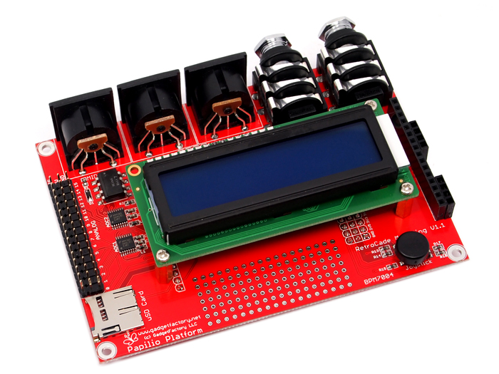
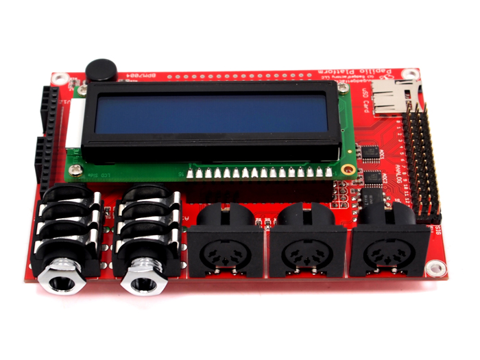
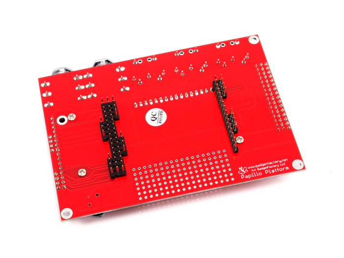
RetroCade MegaWing
The Open Source RetroCade MegaWing provides all of the audio hardware needed to make sweet retro music in one convenient and easy to connect circuit board. It snaps into the Papilio Pro and gives it the necessary hardware resources to communicate with the outside world. Continue reading for more information about each hardware section of the RetroCade MegaWing.
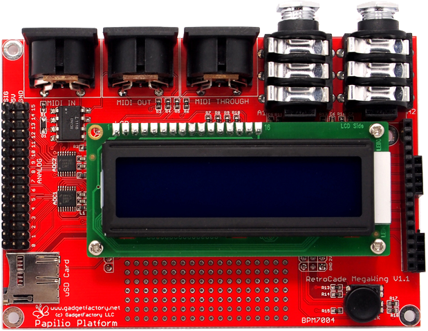
- 2 � �� Stereo Audio Jacks with 18 bit Delta Sigma DAC
- MIDI � In, Out, Through
- uSD Card for MOD, MIDI, YM, SID, and config files
- MicroJoystick � 4 directions, Select
- 2x16 LCD Display
- 16 Analog inputs for sliders and knobs
- 16 Digital inputs for switches and peripherals
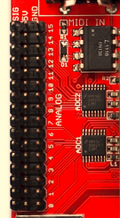
MegaWing MIDI
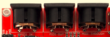
The Midi section of the RetroCade MegaWing implements three MIDI jacks; MIDI IN, MIDI OUT, and MIDI THROUGH. MIDI In is used to connect MIDI instruments such as a MIDI Keyboard, MIDI control board, or MIDI sequencer to the RetroCade synth to send MIDI notes and Control Changes that tell the RetroCade what audio to output. MIDI Through is connected to the MIDI In port and passes everything that comes in over the MIDI In port back out so MIDI devices can be daisy chained together. MIDI Out can be used by the RetroCade to output MIDI data such as timing, change control's or notes.
| Name | Function | Direction | Arduino Pin | Papilio Wing Pin | Papilio Pro Pin | Papilio One Pin |
| MIDI TX | MIDI Out Connector | Output | 32 | C0 | P114 | P91 |
| MIDI RX | MIDI In Connector | Input | 33 | C1 | P115 | P92 |

Technical Details
The RetroCade MIDI implementation is closely patterned after the recommended MIDI circuit implementation provided by the MIDI Manufacturers Association. The only deviation from the recommended design is the use of a 3.3V power connection instead of 5V on the MIDI Out connector. This is necessary since the Papilio Pro uses 3.3V voltage levels instead of 5V levels.
MegaWing Sound
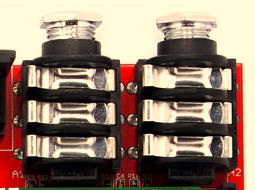

Since sound is the most important aspect of the RetroCade Synth we have gone all out with the audio section. Two top of the line 1/4" Neutrik audio jacks (datasheet) are used to ensure solid high quality audio connections. A low pass filter combined with a high speed Delta-Sigma DAC, as outlined in Xilinx App Note 154, allows high quality audio output to be realized. The high speed of the FPGA clock allows the FPGA to do the heavy lifting of the Digital to Analog conversion.
| Name | Function | Direction | Arduino Pin | Papilio Wing Pin | Papilio Pro Pin | Papilio One Pin |
| A1-Left | Audio Jack 1 Left Channel | Output | 17 | B1 | P97 | P83 |
| A1-Right | Audio Jack 1 Right Channel | Input | 16 | B0 | P99 | P85 |
| A2-Left | Audio Jack 2 Left Channel | Output | 18 | B2 | P92 | P78 |
| A2-Right | Audio Jack 2 Right Channel | Input | 19 | B3 | P87 | P71 |
MegaWing Character LCD
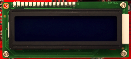
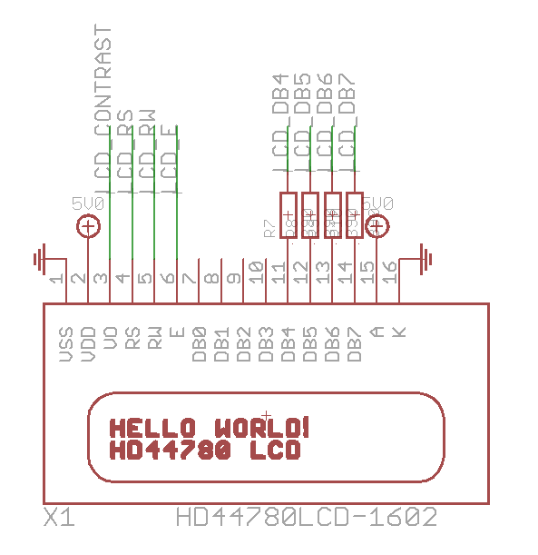
A 16x2 HD44780 compatible Character LCD is used to provide standalone control and feedback for the RetroCade. A standard backlight is provided for easy visibility in low light situations.
| Name | Function | Direction | Arduino Pin | Papilio Wing Pin | Papilio Pro Pin | Papilio One Pin |
| LCD_Contrast | Contrast adjustment | Output | 46 | C14 | P133 | P16 |
| LCD_RS | Register Select (RS). RS=0: Command, RS=1: Data | Output | 26 | B10 | P62 | P41 |
| LCD_RW | Read/Write (R/W). R/W=0: Write, R/W=1: Read | Output | 25 | B9 | P95 | P54 |
| LCD_E | Clock (Enable). Falling edge triggered | Output | 24 | B8 | P74 | P58 |
| LCD_DB4 | Bit 4 | Output | 23 | B7 | P78 | P61 |
| LCD_DB5 | Bit 5 | Output | 22 | B6 | P80 | P63 |
| LCD_DB6 | Bit 6 | Output | 21 | B5 | P82 | P66 |
| LCD_DB7 | Bit 7 | Output | 20 | B4 | P84 | P68 |
MegaWing Joystick
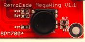
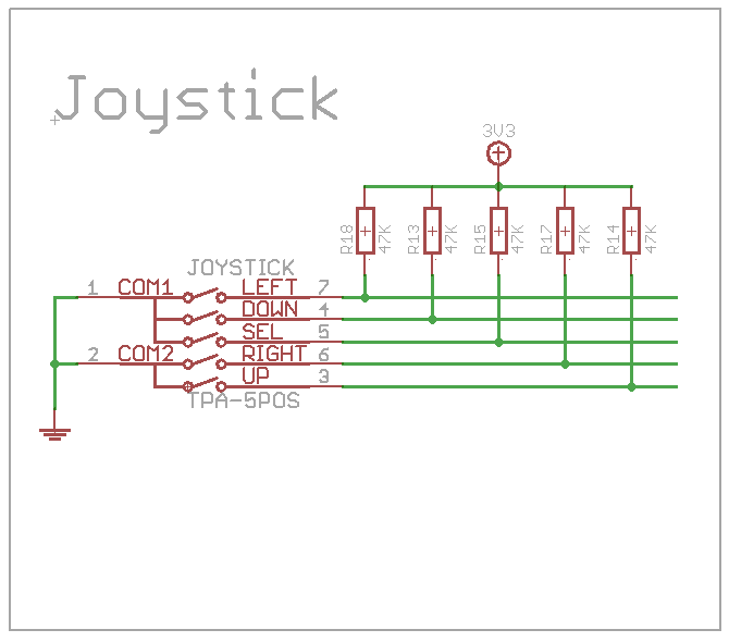
A really slick TPA511GLFS digital joystick is included to make navigating menu's a snap. It provides four directions and select in a compact fingertip controlled form factor.
| Name | Function | Direction | Arduino Pin | Papilio Wing Pin | Papilio Pro Pin | Papilio One Pin |
| Joy_Left | Joystick Left | Input | 28 | B12 | P57 | P34 |
| Joy_Down | Joystick Down | Input | 29 | B13 | P55 | P32 |
| Joy_Select | Joystick Select | Input | 31 | B15 | P47 | P22 |
| Joy_Right | Joystick Right | Input | 27 | B11 | P59 | P36 |
| Joy_Up | Joystick Up | Input | 30 | B14 | P50 | P25 |
MegaWing MicroSD

The MicroSD (Secure Digital) socket expands the RetroCade with GigaBytes worth of storage space for your audio and configuration files. SD Fat libraries over the standard SPI interface allows files to be copied directly from your computer's filesystem onto an uSD card that can be read by the RetroCade.
| Name | Function | Direction | Arduino Pin | Papilio Wing Pin | Papilio Pro Pin | Papilio One Pin |
| SD_DO | Data Out [MISO] | Input | 42 | C10 | P126 | P10 |
| SD_DI | Data In [MOSI] | Output | 44 | C12 | P131 | P12 |
| SD_SCK | Clock [SCLK] | Output | 43 | C11 | P127 | P11 |
| SD_nCS | Card Select (Active Low) | Output | 45 | C13 | P132 | P15 |
MegaWing Analog Input
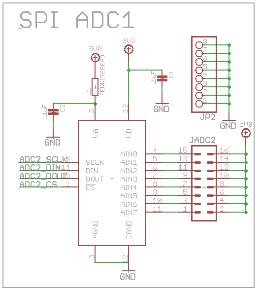
16 Analog inputs allow the RetroCade to be turned into a custom controller to implement your wildest controllerism ideas. The Analog header allows you to connect up to sixteen analog devices such as sliders, knobs, and analog joysticks. The header is even compatible with the Seeed Studio analog Grove devices when used with a Grove to Brick adapter. Easily add Grove Sliders, Grove Joysticks, or any other Analog Grove device.
The 16 analog channels are implemented with two ADC088S102CIMTX 8-bit, 8 Channel, SPI ADC's that are capable of sampling at speeds up to 1Msps.
| Name | Function | Direction | Arduino Pin | Papilio Wing Pin | Papilio Pro Pin | Papilio One Pin |
| ADC1_SCLK | Clock [SCLK] | Output | 34 | C2 | P116 | P94 |
| ADC1_DIN | Data In [MOSI] | Output | 36 | C4 | P118 | P98 |
| ADC1_DOUT | Data Out [MISO] | Input | 35 | C3 | P117 | P95 |
| ADC1_nCS | Card Select (Active Low) | Input | 37 | C5 | P119 | P2 |
| ADC2_SCLK | Clock [SCLK] | Output | 38 | C6 | P120 | P3 |
| ADC2_DIN | Data In [MOSI] | Output | 40 | C8 | P123 | P5 |
| ADC2_DOUT | Data Out [MISO] | Input | 39 | C7 | P121 | P4 |
| ADC2_nCS | Card Select (Active Low) | Input | 41 | C9 | P124 | P9 |
License

RetroCade MegaWing is licensed under a Creative Commons Attribution-ShareAlike 3.0 Unported License.
RetroCade MegaWing copyright Jack Gassett, Gadget Factory.
Links
Images

RetroCade MegaWing
Click the images for full size hi-resolution views of the RetroCade MegaWing.
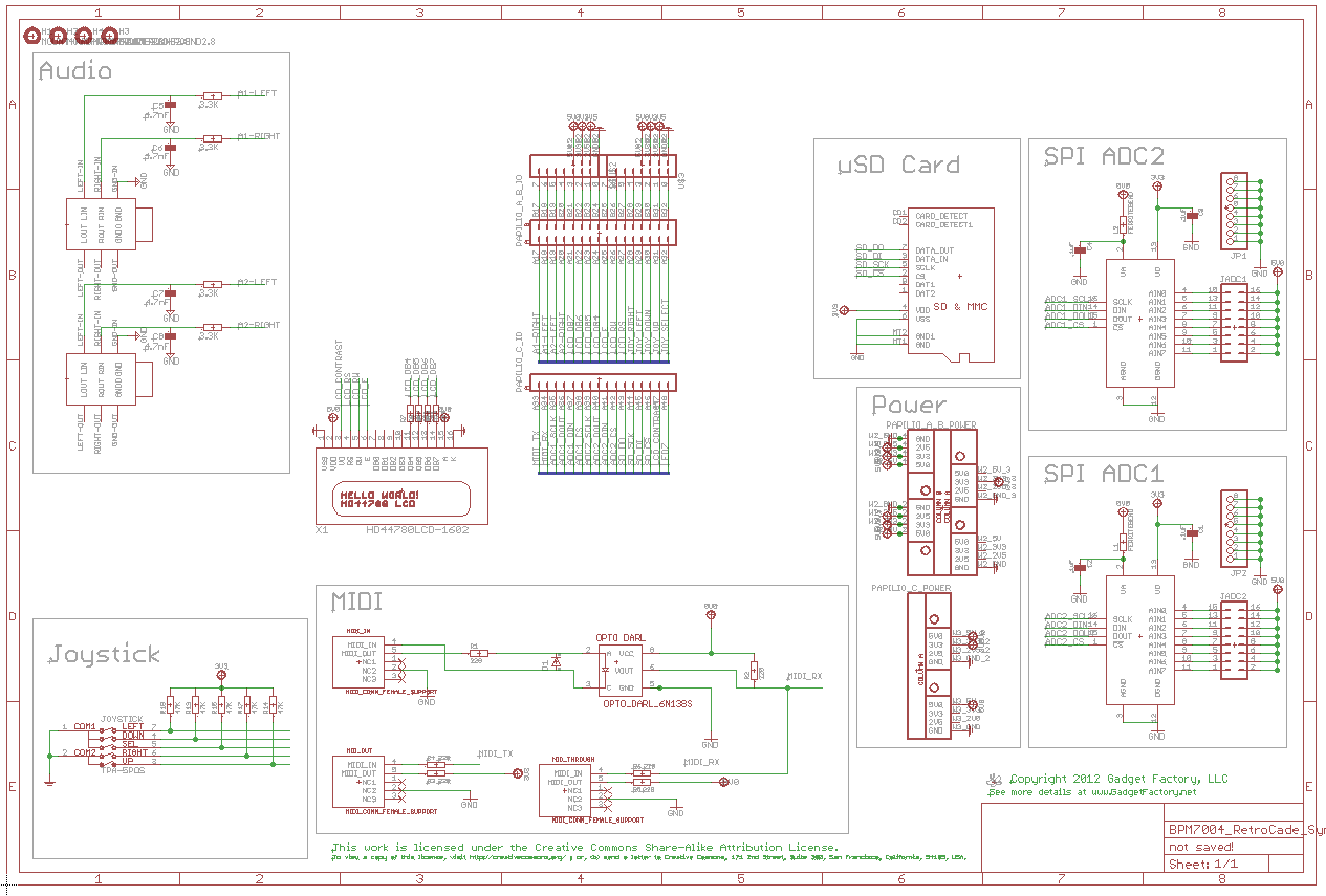
RetroCade MegaWing Schematic
Click the image to load a PDF version of the RetroCade MegaWing Schematic

Assembly View
Click the image for a full size view of the boards part layout.